MAKING THE CONTROLLER
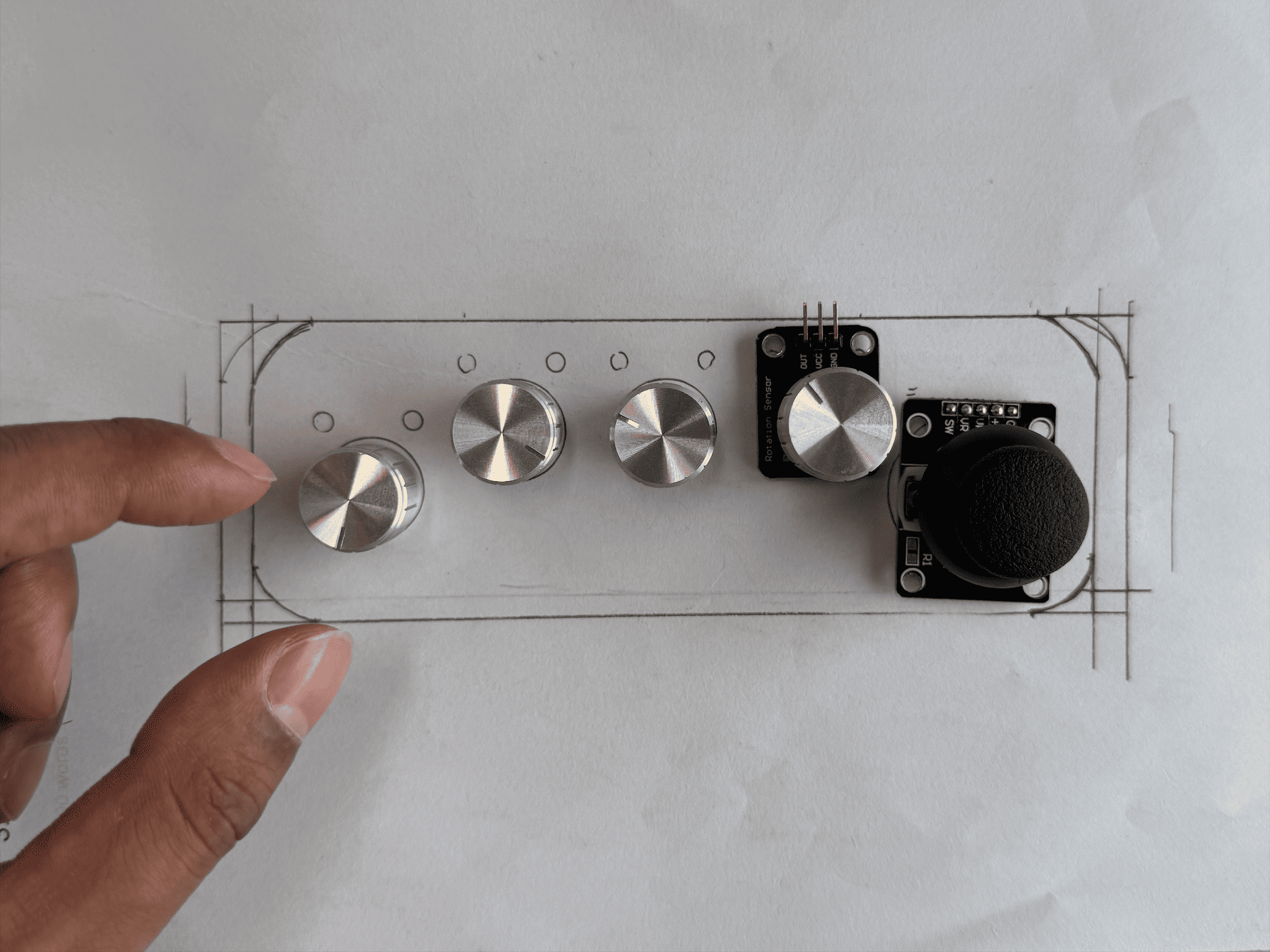
This week, I directed my focus entirely on making the controller. I began by sketching multiple layout variations for the four potentiometers and one joystick. After exploring several arrangements, I settled on a configuration where the potentiometers were aligned in a row, with the joystick positioned on the right-hand side for ergonomic access.
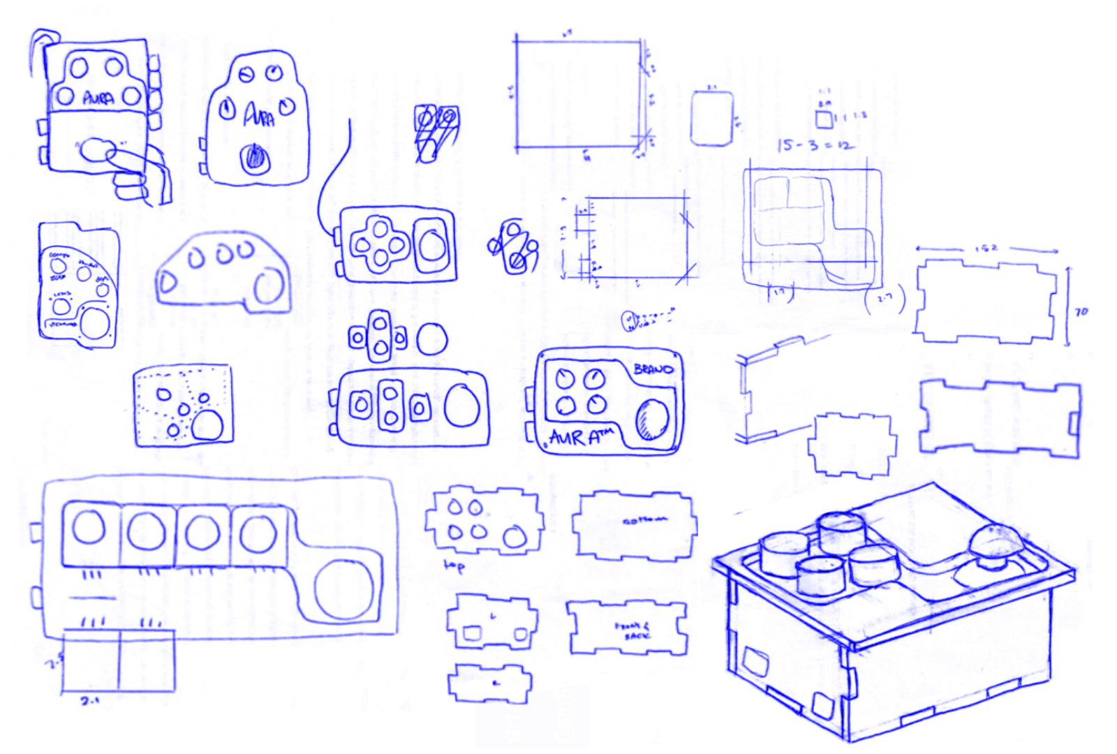
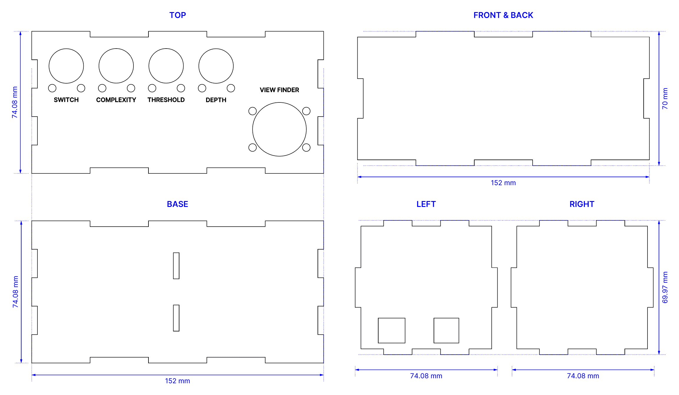
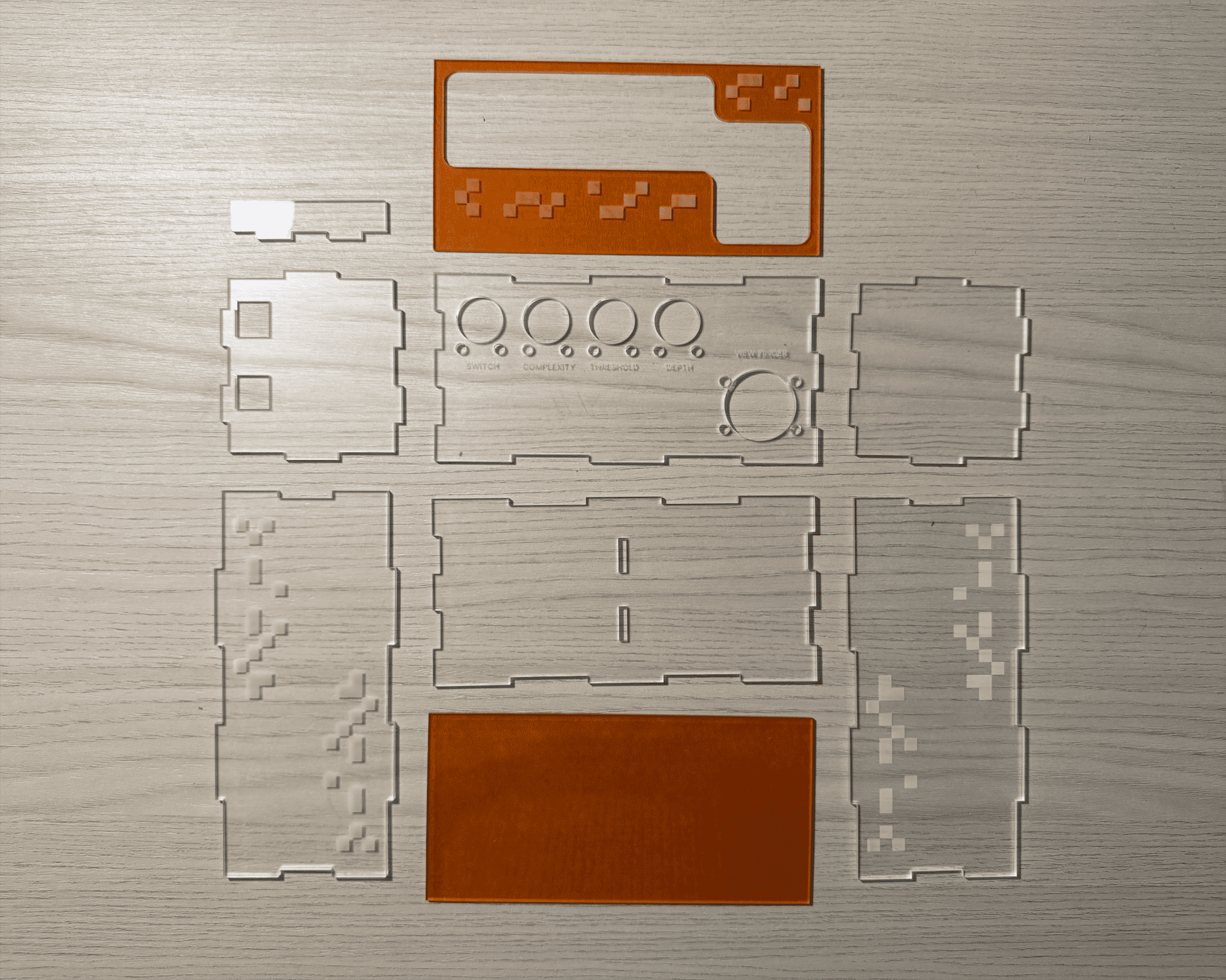
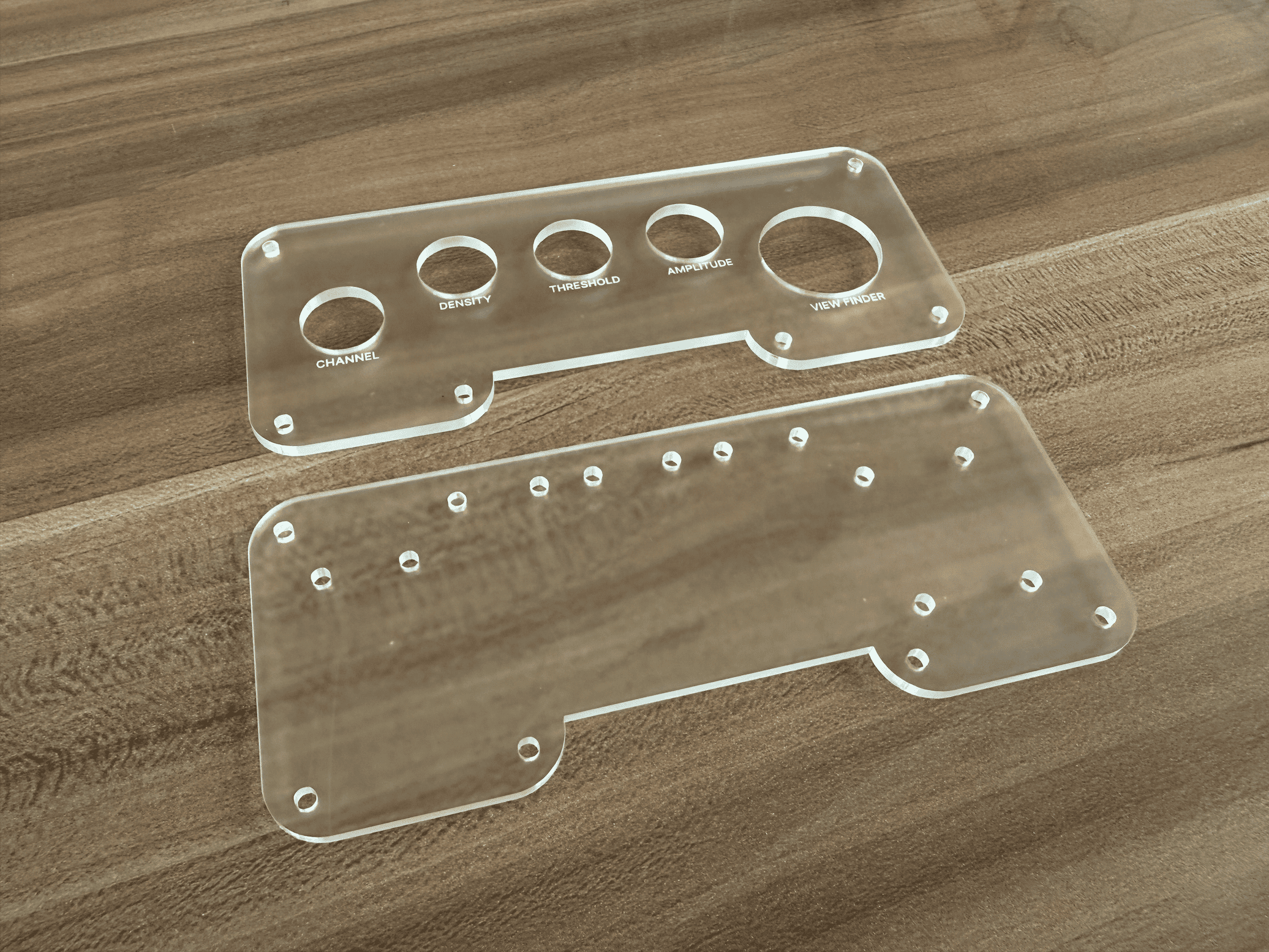
What consumed most of my time, however, was not the layout itself but the precision required in translating the sketch into a workable casing. Measuring diameters for screw holes, ensuring ample space for knobs and planning connector joints for the acrylic panels required meticulous attention. I brought the design into Adobe Illustrator to draft a popper blueprint for laser cutting.
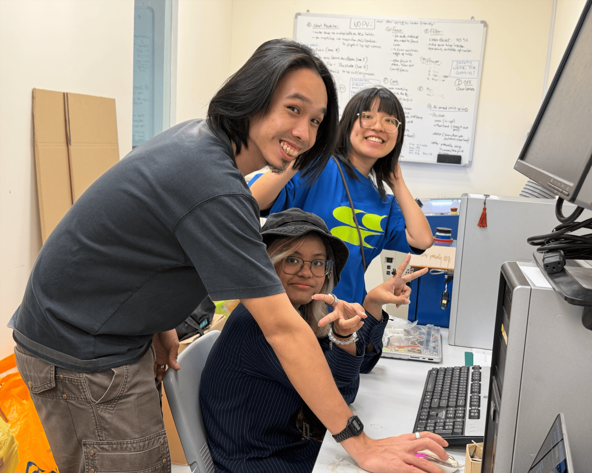
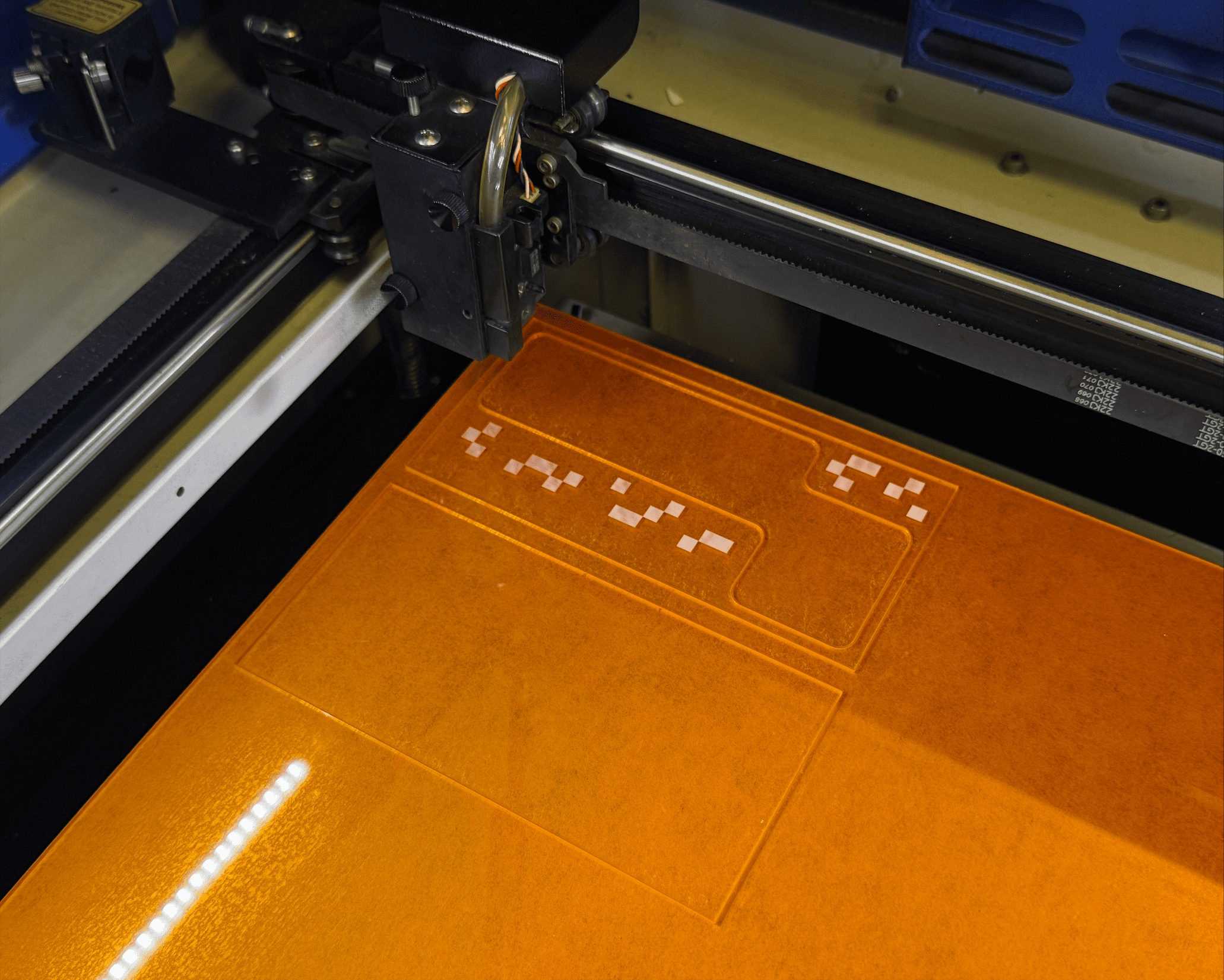
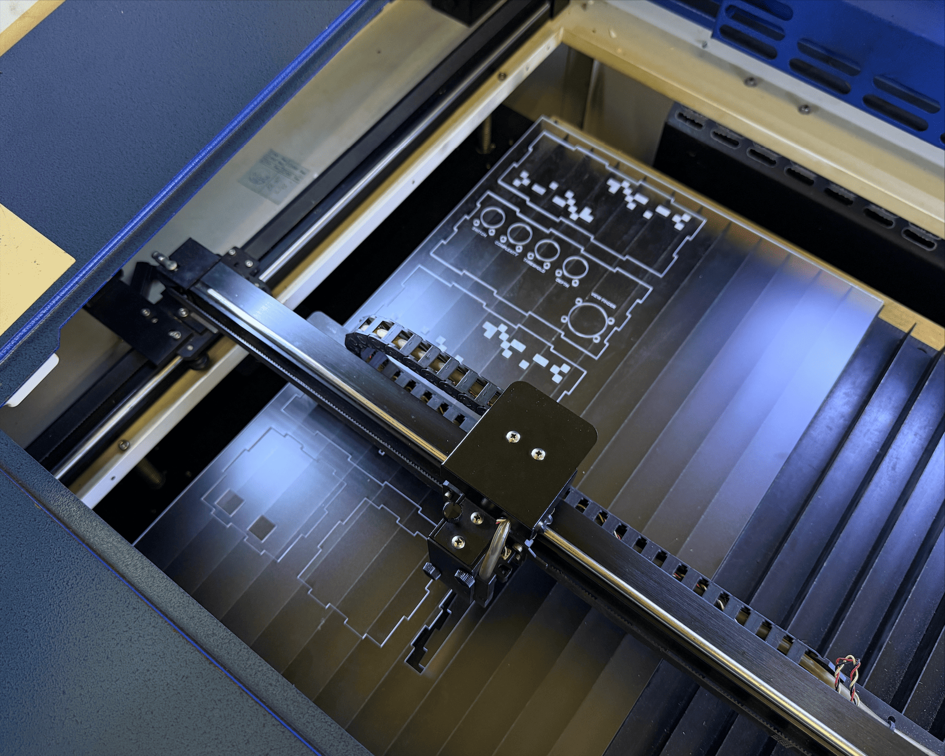
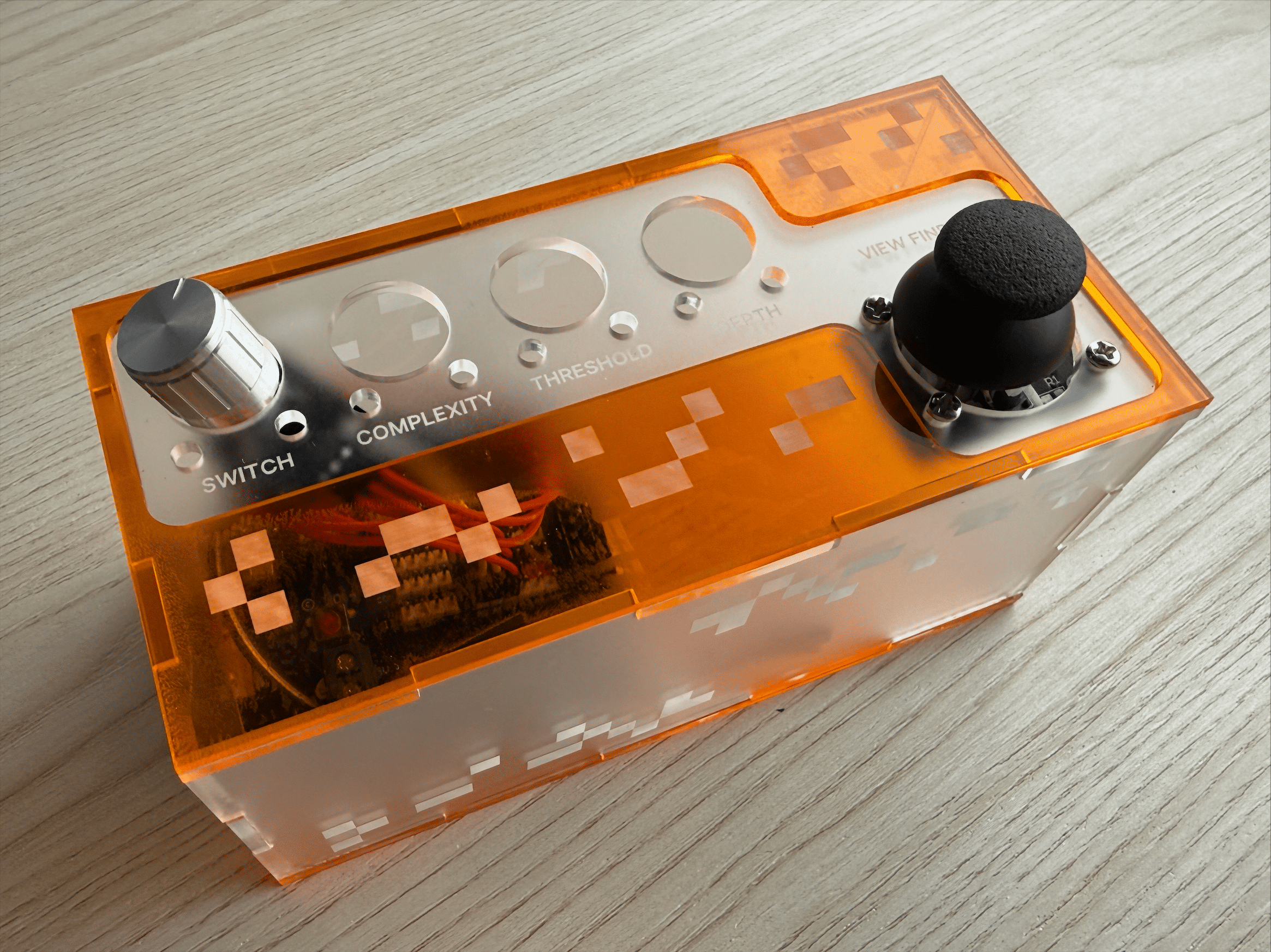
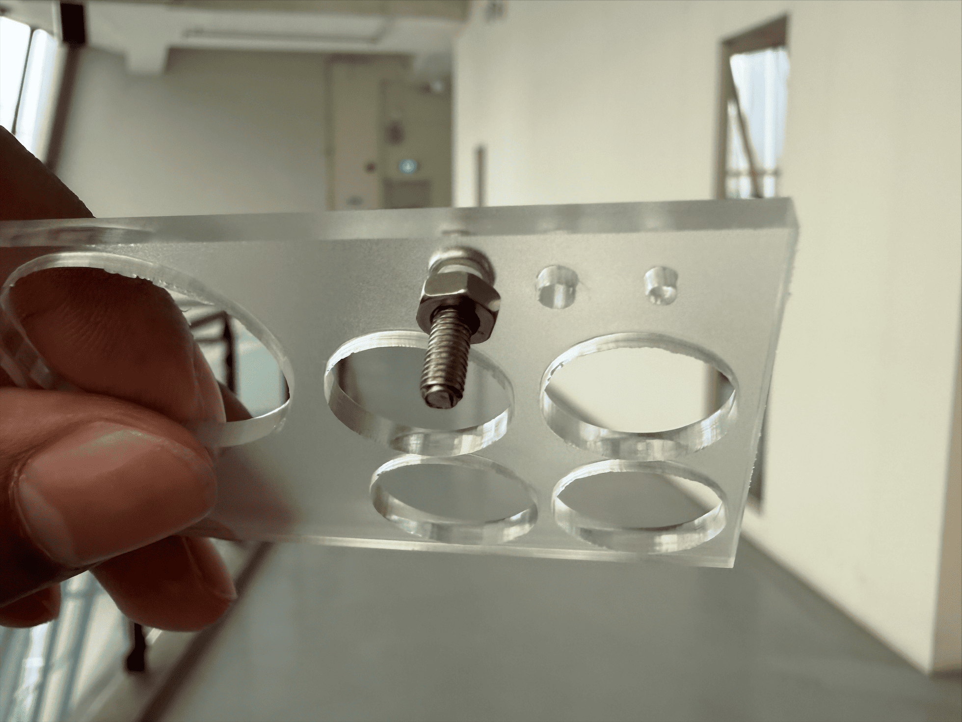
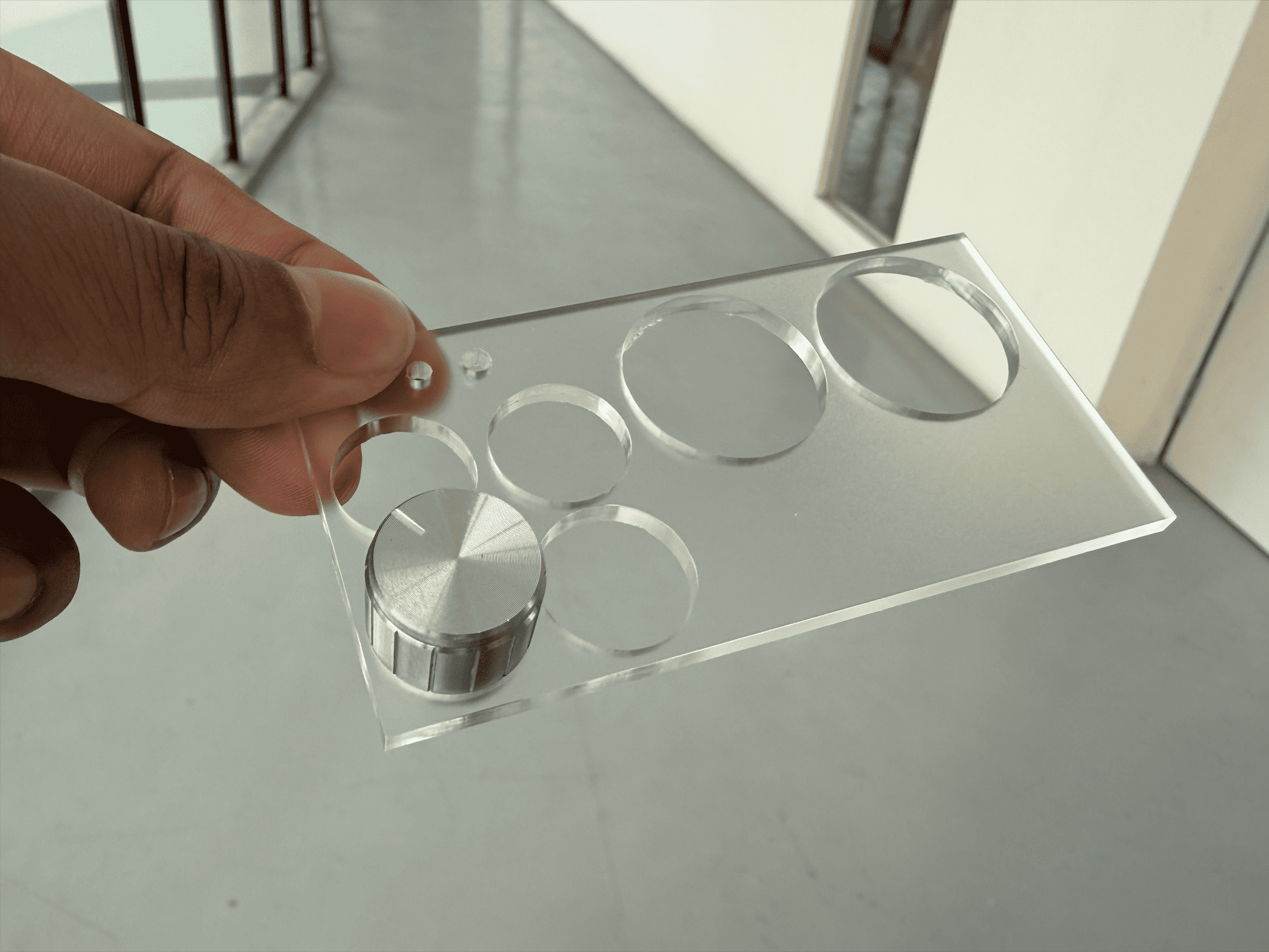
Thankfully, I was able to join my classmates’ during their laser cutting session. There were several rounds of testing to determine the correct power and speed settings before cuting the actual pieces. I chose frosted white acrylic for the main body and transparent orange acrylic for accents, hoping to achieve a clean yet slightly futuristic aesthetic.
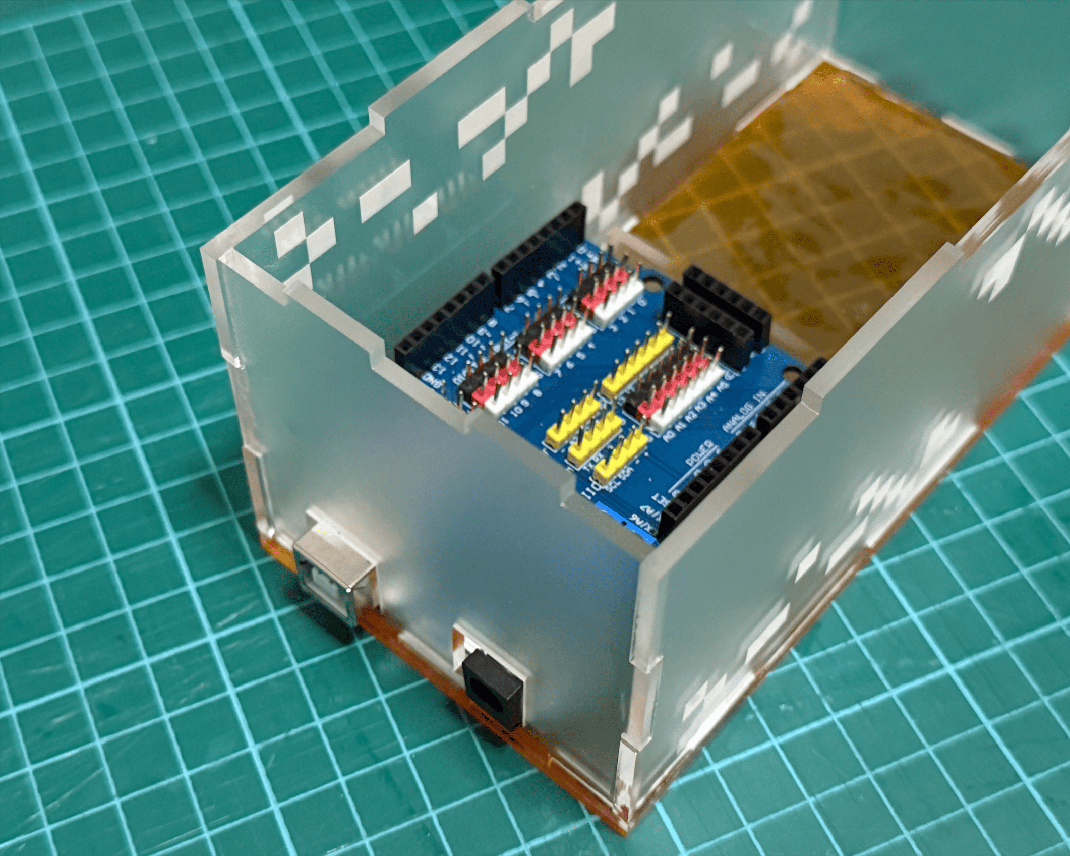
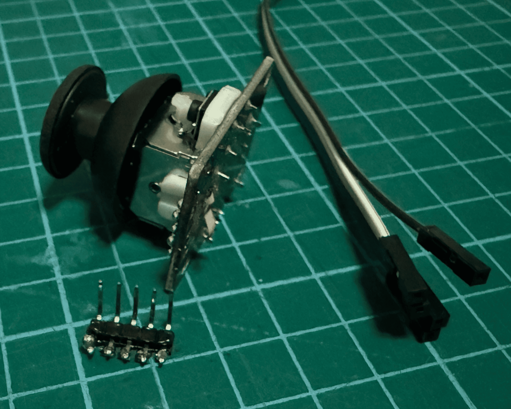
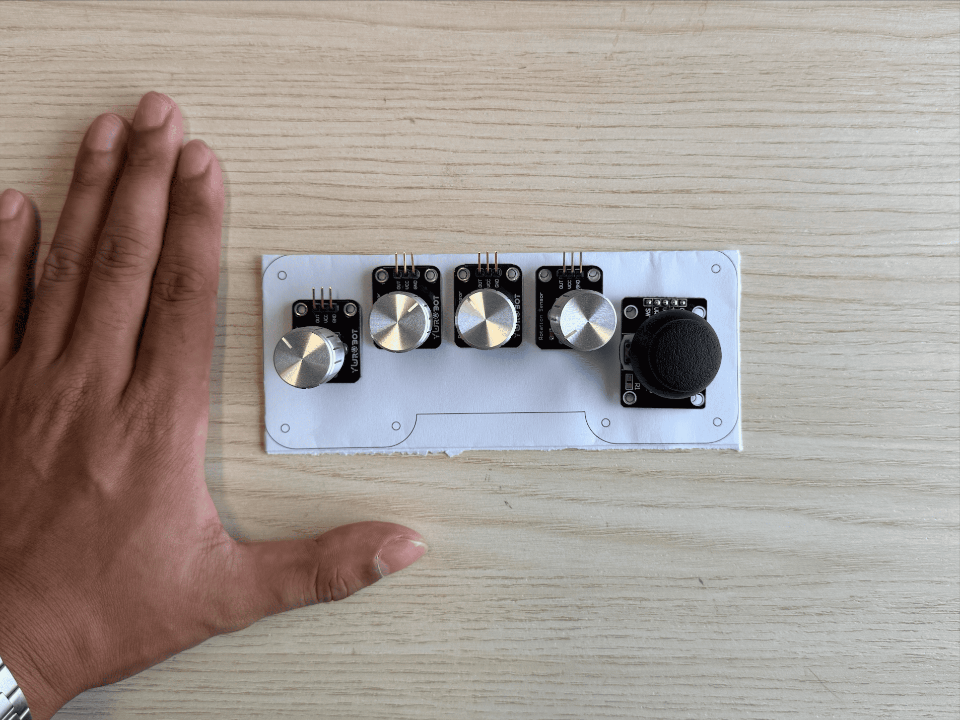
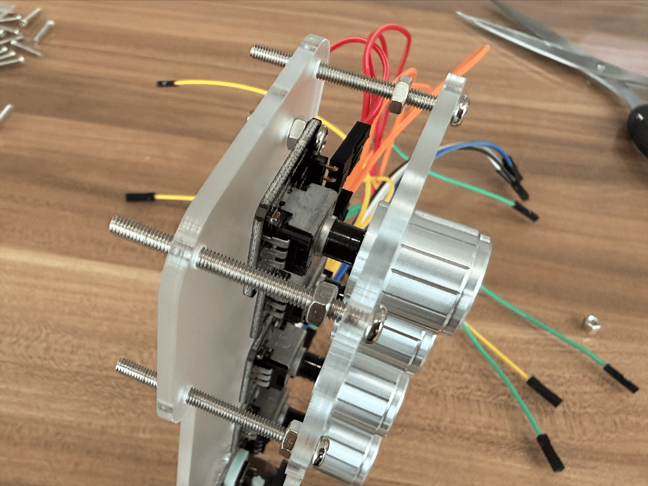
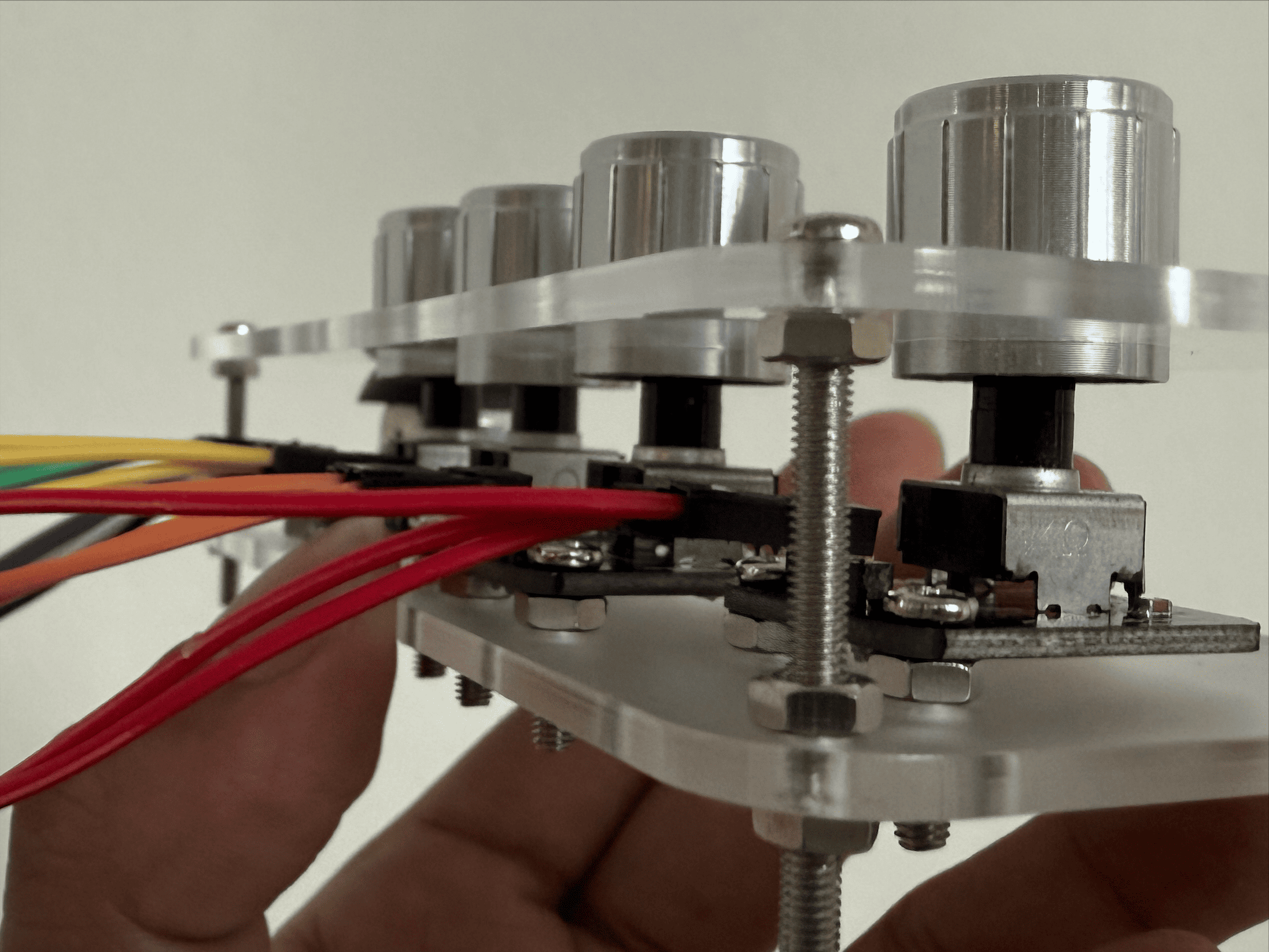
Before even assembling the first prototype, I was already confronted with multiple design flaws. Some holes were misaligned due to parallax errors during measurement. Several were too large for the screws and caps, causing instability. More critically, I failed to account for the height of the module pins on the module. As a result, when mounted, the module pins were hitting against the underside of the acrylic and I could not screw the components tightly, causing the components to dangle awkwardly.
Carissa suggested desoldering the module pins and re-soldering them beneath the module so the components could sit flush against the acrylic. I was eager to attempt this because I wanted the modules hidden for a more refined look. However, we underestimated how time-consuming and delicate the desoldering process would be. Despite everyone’s help, the joystick module eventually stopped functioning and the serial data became unstable. The module was likely damaged from prolonged heat exposure.
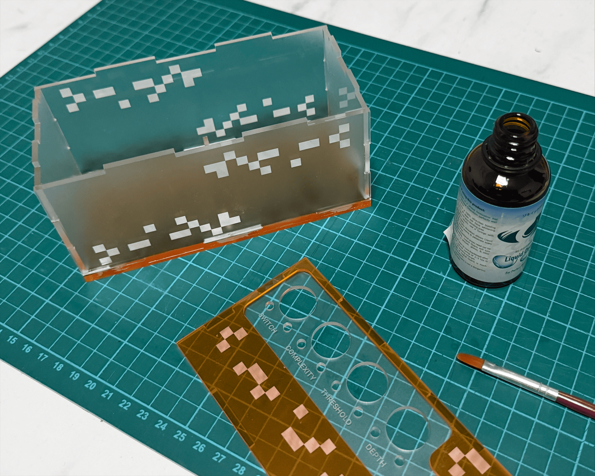
At that point, I felt frustrated. The miscalculations, the failed soldering attempt and the compromised joystick made the prototype feel unsuccessful. The only thing working well was the acrylic glue because the structure was surprisingly sturdy. This moment reminded me how prototyping is often less about perfection and more about uncovering hidden constraints.
“JUST EXPOSE IT”
During consultation, I voiced my concerns about the unfinished appearance of the controller. My intention had been to conceal the electronics to create a polished, product-like object. However, Andreas reminded me that this is a prototype, not a maket-ready product. As design communicators, our role is not necessarily to produce commercial objects but to test and communicate ideas. Although this lowered the pressure slightly, I still wanted the controller to feel intentional and well-crafted. I therefore identified two priorities:
① Redesign the shape for better ergonomics. The existing casing felt bulky and the sharp corners were uncomfortable to hold.
② Accept that exposing the Arduino, or not enclosing it at all, might be part of the prototype’s honesty rather than a flaw.
This shift in mindset helped me detach from the need for aesthetic perfection and focus instead on usability and clarity of concept.
REFINING THE DESIGN
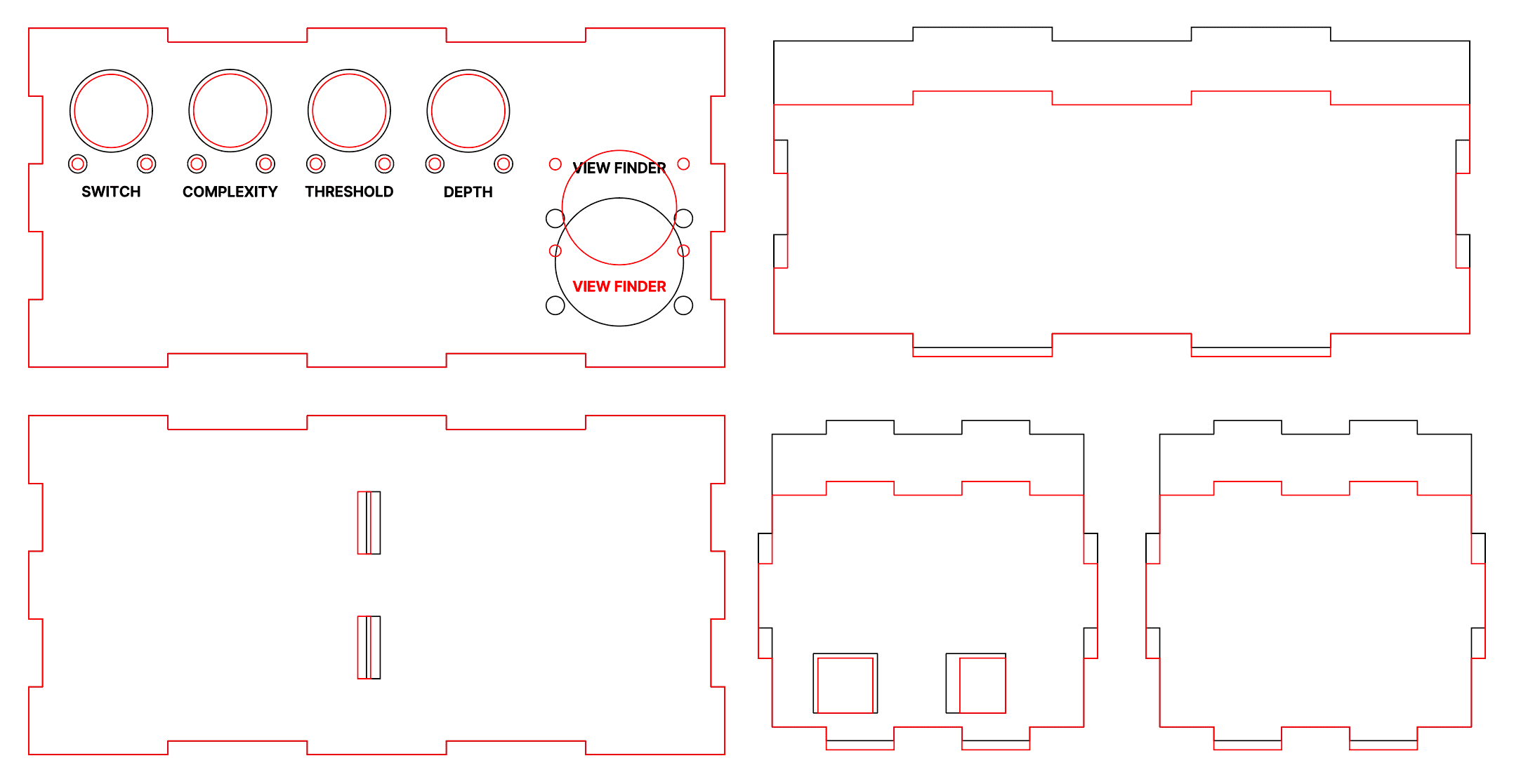
I began redrafting the casing with reduced dimensions and recalibrated hole measurements. Initially. I was merely resizing the original design without rethinking its form. Realising this, I paused and reconsidered the object entirely. Interestingly, I noticed that the top acrylic layer alone actually felt comfortable in my hand, ignoring its sharp edges.
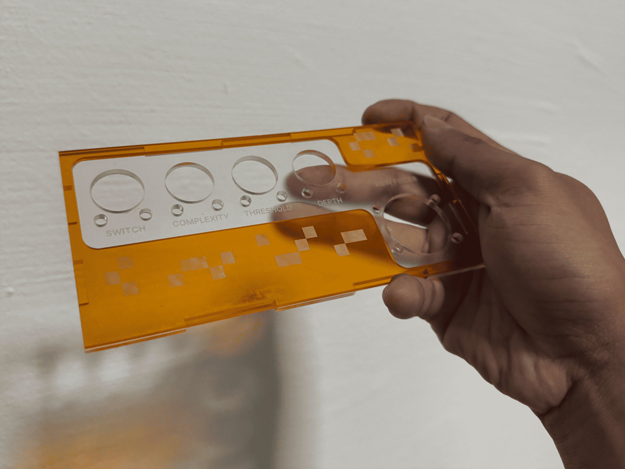
I began to work with the components on paper, sketching compact shapes around the components. I rounded the corners and refined the silhouette to resemble something closer to a handheld gaming console (smaller, softer and more intuitive to grip).
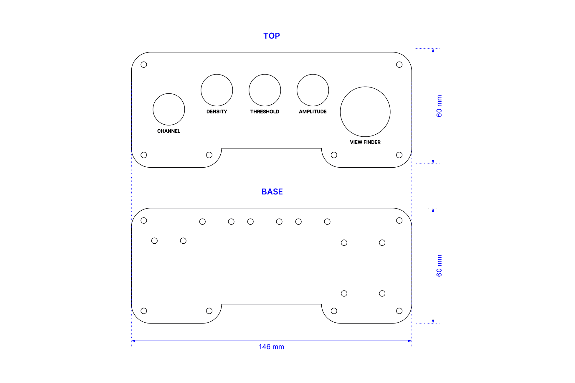
Before committing to a full laser cut, I created a test strip with multiple hole diameters for comparison. Screw holes ranged from 2.5mm to 3.5mm (previously 4mm), potentiometer holes ranged from 16mm to 17.5mm (previously 18mm) and joystick openings ranged between 26mm to 27mm (previously 28mm). This calibration test allowed me to make informed adjustments before cutting the final version.
With updated measurements, I assembled the new controller using bolts and nuts. I was slightly anxious that tightening the screws would crack the acrylic, but fortunately everything held together well. The final outcome felt significantly more refined and proportionate compared to the first attempt.
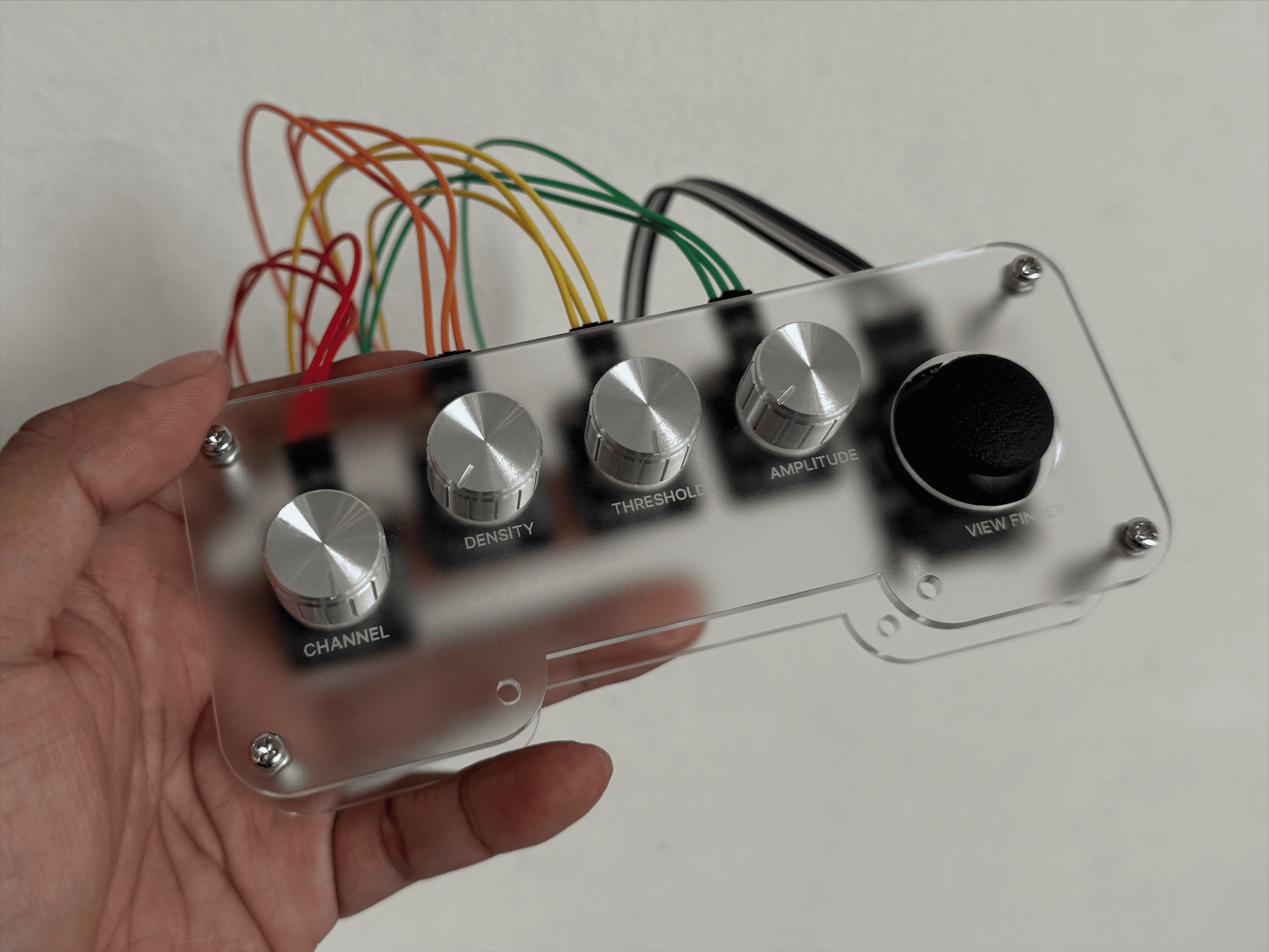
One final technical adjustment remained: due to the repositioning of the joystick, I needed to re-pin the jumper wires to prevent tension on the connections. This required updating the Arduino input mapping and reconfiguring the Serial DAT in TouchDesigner to ensure the correct channels were referenced.